


I built a cluster using Raspberry Pi 5s to experiment with cluster computing and AI.
You can check out some of the things I have computed with my Raspberry Pi 5 Cluster such as Prime Numbers and Mandelbrot Set images and movies.
If you are interested in how I built the cluster keep reading!
Parts List
| Quantity | Product | Unit Cost | Total Cost |
|---|---|---|---|
| 8 | Raspberry Pi 5 16GB single board computers | $120 | $960 |
| 8 | WaveShare PCIe to M.2 Adapter with PoE | $31 | $248 |
| 8 | ORICO M.2 2242 NVMe SSD 256GB | $30 | $240 |
| 1 | SanDisk 64GB Extreme microSDXC UHS-I Memory Card | $11 | $11 |
| 2 | Cloudlet Cluster Case | $90 | $180 |
| 1 | GigaPlus 10 Port 2.5Gb Unmanaged PoE Switch | $110 | $110 |
| 1 | REDLUX 2.5/5/10G SFP+ to RJ45 Module | $28 | $28 |
| 1 | Tripp Lite 850VA UPS Desktop Battery Backup | $150 | $150 |
| 1 | Delinx 36W 12V PC Fan Power Supply | $17 | $17 |
| 1 | WINSINN 50mm Fan 12V, pack of 5 | $18 | $18 |
| 1 | GearIT Cat 6 Ethernet Cable (10-Pack 1 Foot) | $19 | $19 |
| 1 | Raspberry Pi Monitor | $100 | $100 |
| 1 | Raspberry Pi 15W Power Supply | $8 | $8 |
| 1 | Micro-HDMI HDMI cable 4/5, 3ft | $5 | $5 |
| 1 | Raspberry Pi Official Keyboard | $20 | $20 |
| 1 | Raspberry Pi Official Mouse | $9 | $9 |
| 1 | Raspberry Pi 27W USB-C Power Supply | $14 | $14 |
| 1 | ARCTIC MX-4 (4 g) - Premium Performance Thermal Paste (Recommended) | $7 | $7 |
| 1 | Anti Static Mat (Optional) | $15 | $15 |
| Total | $2137 |

Building the Cluster
The 8x Raspberry Pi 5 SBCs will need to be mated with the WaveShare PCIe to M.2 HATs (Hardware Attached on Top). The process is as follows:
Start with the Raspberry Pi 5 SBC. The Raspberry Pi 5 and hats are fairly resistant to static but if you are concerned be sure to assemble on an antistatic mat or use an antistatic wrist strap

The WaveShare PCIe to M.2 HAT comes with three thermal pads (pink rectangles) that should be attached to three of the main chips on the SBC. The main SoC (System on a Chip) is the largest silver colored chip in the middle of the board. This is the brains of your Raspberry Pi 5. It sits up higher and will contact directly with the heatsink. Three other chips sit lower and need the thermal pads so that they can make contact with the heat sink. They are the RAM (directly north of the SoC), the WiFi/Bluetooth chip (northwest of the SoC) and the cluster of smaller chips that comprise the PMIC (Power Management IC) (southwest corner of the SBC). You will use the largest of the three thermal pads for the PMIC. The remaining chip is the IO controller (northeast of the SoC) but we won’t put a thermal pad on it because the heat sink supplied does not cover this chip. Recommended: If you are concerned that the main SoC might have an air gap with the heatsink you can apply a drop of ARCTIC MX-4 Thermal Paste to the center of the chip. My Raspberry Pi 5s run much cooler with the Thermal Paste applied vs without.

Each side of the thermal pads is covered with a thin plastic film. You must remove this film from both sides when attaching them. It is easiest to use a small pocket knife to remove the film from one side, then affix it to a chip. Then use your knife to remove the top layer of film so that the sticky pad will adhere to both the chip and the heatsink. Once the thermal pads are attached you can attach the heat sink. It comes with two spring loaded pins that must be pushed through the SBC circuit board. Align the pins with the holes in the SBC and firmly push them through. It can take quite a bit of force but once you hear them snap they are though.

The WaveShare PCIe to M.2 HAT comes with four brass standoffs and eight screws. We will use four of these screws to attach the standoffs to the HAT. We will not be using the other four screws as the Cloudlet Cluster Case comes with some longer screws that we will need to attach the Raspberry Pi 5 to the mounting bracket.

There is a small cable of wires that comes off the cooling fan on the HAT. Attach the plug on the end of the wires to the fan control socket on the SBC circuit board. It is on the northeast corner of the SBC between the 40 pin GPIO header and the top USB connector. There is a small cap on the socket that can be removed with a small knife. Look at the four pin holes on the plug and match them to the four pins in the socket. The plug/socket is directional, i.e. it only fits properly one way. Push the plug in as far as it will go but it will not go all the way down.

Now we are ready to attach the WaveShare PCIe to M.2 HAT to the Raspberry Pi 5 SBC. Align the 40 pin socket with the 40 pin GPIO pins at the north edge of the SoC. Also note that there is a 4 pin socket that mates with the 4 pin PoE header in the southeast corner just to the left of the Ethernet port. Push the HAT down a little on each side until it is completely down.

Now we have to attach the 40mm PCIe ribbon cable to the HAT and SBC. The connectors are on the west side of the combined boards. The top connector on the HAT flips up to open. The bottom connector on the SBC pulls up. These are very small connectors so a knife blade can help.

Insert the ribbon cable into the bottom connector. Be sure to orient the cable correctly. The printed writing side should face out and the small triangle on the edge of the ribbon cable should match the small triangle on the HAT. Carefully push the bottom connector down to lock the cable in place. Then insert the ribbon cable in the top connector and then flip the connector down to lock.

We can now attach the combined SBC and HAT to a Cloudlet Cluster Case mounting plate. Use four of the longer screws that come with the case. Place the four screws through the mounting plate then attach the plate to the SBC with the screws.

Note that the two prongs on the mounting bracket should be on the same side as the PCIe ribbon cable and the quick release tab on the mounting bracket should be next to the top USB socket.

Finally attach the M.2 NVMe SSD to the socket on the HAT. Use the supplied screw to hold the SSD down. We can now test the assembly using a Raspberry Pi 27W USB-C power supply or using an ethernet cable connected to our PoE switch. Attach the monitor, keyboard and mouse.

Download the Raspberry Pi Imager application on another computer and use that program to install the 64-bit Raspberry Pi OS onto the 64GB micoSD card. We will use this microSD card to install the Raspberry Pi OS onto the eight NVMe SSDs one at a time.

Once you click next, you will be given the option to edit the settings for the OS. Click “Edit Settings”. In this dialog configure the hostname such as “balrog0”. All my cluster nodes will be named using this pattern “balrog1”, “balrog2”, etc. Then set the user name and password that you want to use for the admin account on all the nodes of the cluster. Configure the WIFi and time zones, then click “Save”.

Once the microSD card is imaged, put it into the SD slot of the Raspberry PI 5 we just assembled and plug the power in to boot it up. It should boot right into the Linux desktop. Now we can install some software that we want to be on all the nodes.
$ sudo apt install nala
$ sudo nala install fonts-jetbrains-mono
$ sudo nala install gnome-system-monitor
$ sudo nala install libssl-dev
$ sudo nala install sysstat
$ sudo nala install sshfs
$ sudo nala install pssh
$ sudo nala update
$ sudo nala upgrade
The OpenMPI libraries can be used to write C++ programs that can be distributed across the nodes of the cluster. We will need to download the source for three libraries, compile and install them. The script install_openmpi.sh contains the commands needed to install the software.
From the Raspberry Pi menu in the top left corner, select “Accessories” then “SD Card Copier”. We will use this application to flash the OS onto the SSD. Be sure to select the “/dev/mmcblk0” device as the “Copy From Device” as this is the microSD device. Then select the “/dev/nvme0n1” device as the “Copy To Device”. You must check the box next to “New Partition UUIDs” so that the SSD will have a different UUID (Universally Unique Identifier) so that you can boot from the microSD or SSD as needed without the computer getting them confused.

After you have completed flashing the SSD shutdown the Raspberry Pi 5 and unplug the power. Remove the microSD card and then power the Raspberry Pi 5 up again. It should boot from the SSD now. Once the desktop comes up from the Raspberry Pi menu in the top left corner, select “Preferences” then “Raspberry Pi Configuration”. Under the “System” tab change the hostname to the new name for that node such as “balrog1”, “balrog2”, “balrog3”, etc. Under the “Interfaces” tab be sure to turn on SSH and VNC. Also you will want to launch the terminal and run raspi-config using sudo. Select the “Advanced Options” selection, then “PCIe Speed” option. Turn on “PCIe Gen 3” so that your M.2 SSD will run at full speed.

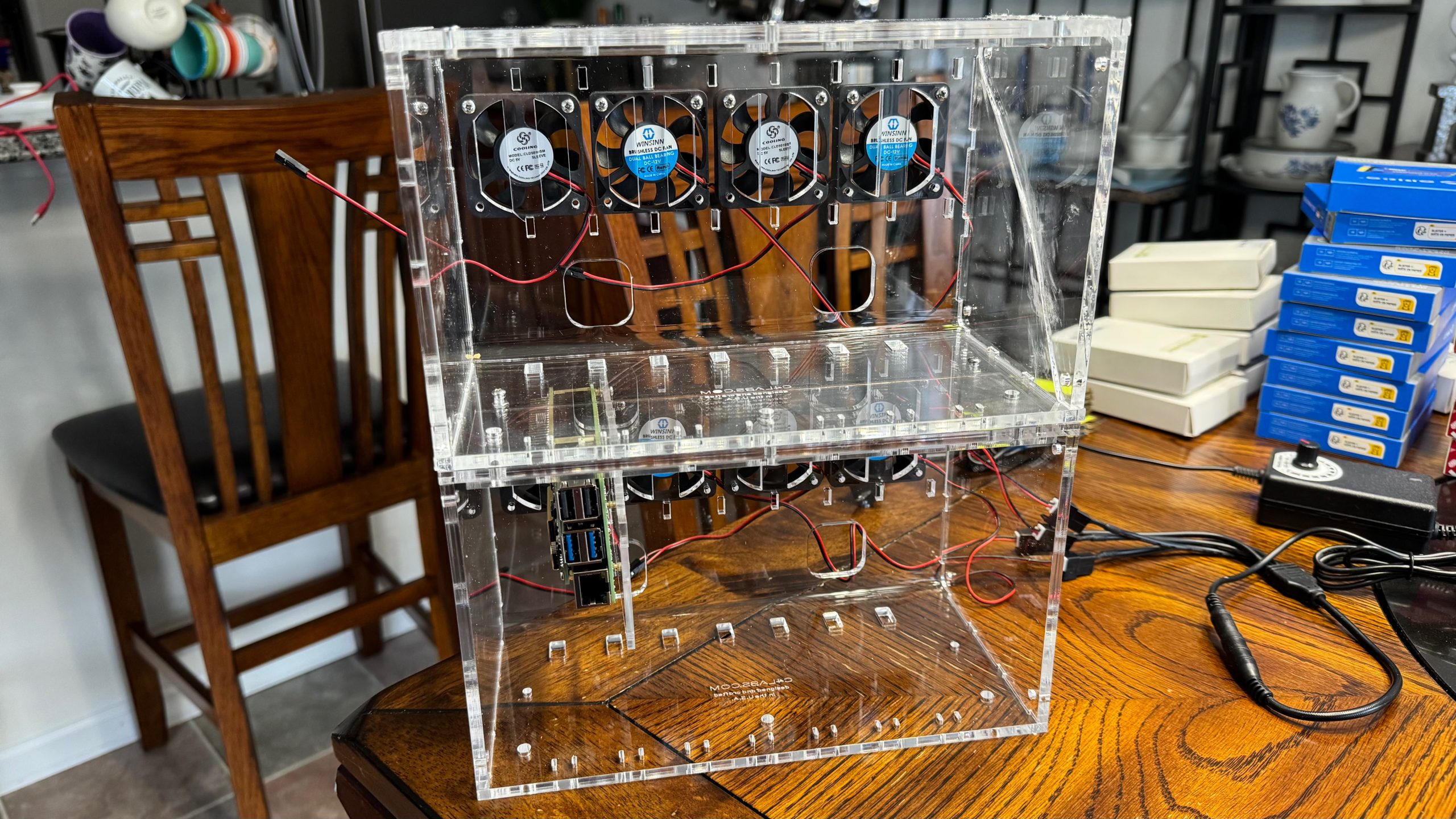
When you have all eight Raspberry Pi 5s assembled and configured we can begin assembling the case. The Cloudlet Cluster Case comes with four 5V fans that can be attached to the GPIO headers on the Raspberry Pi 5. Since we will be pulling power via the Ethernet switch we don’t necessarily want to overload it so externally powered fans are a good alternative. You can get a box of five 50mm 12V fans and a four fan external controller/power supply that will replace the 5V fans that come with the case.

If you do want to use the supplied fans be sure to connect the two leads of each fan to pins 4 and 6 of a nearby Raspberry Pi 5 GPIO header. The red lead attaches to the 5V on pin 4 and the red/black lead attaches to Ground on pin 6.

The Cloudlet Cluster Case claims to have enough room for 8 Raspberry Pi 5’s with PoE HATs but the WaveShare PCIe to M.2 adapter has extended pins for the GPIO header that prevents our assemblies from fitting in one slot. I had to get two cases and mount four Raspberry Pi 5s in each case. After we attach all eight fans we can begin inserting the Raspberry Pi 5s.

Simply insert the two prongs into the slots on the back of the case. Then gently guide the mounting bracket into the slots on the top of the case until the quick release latch clicks.
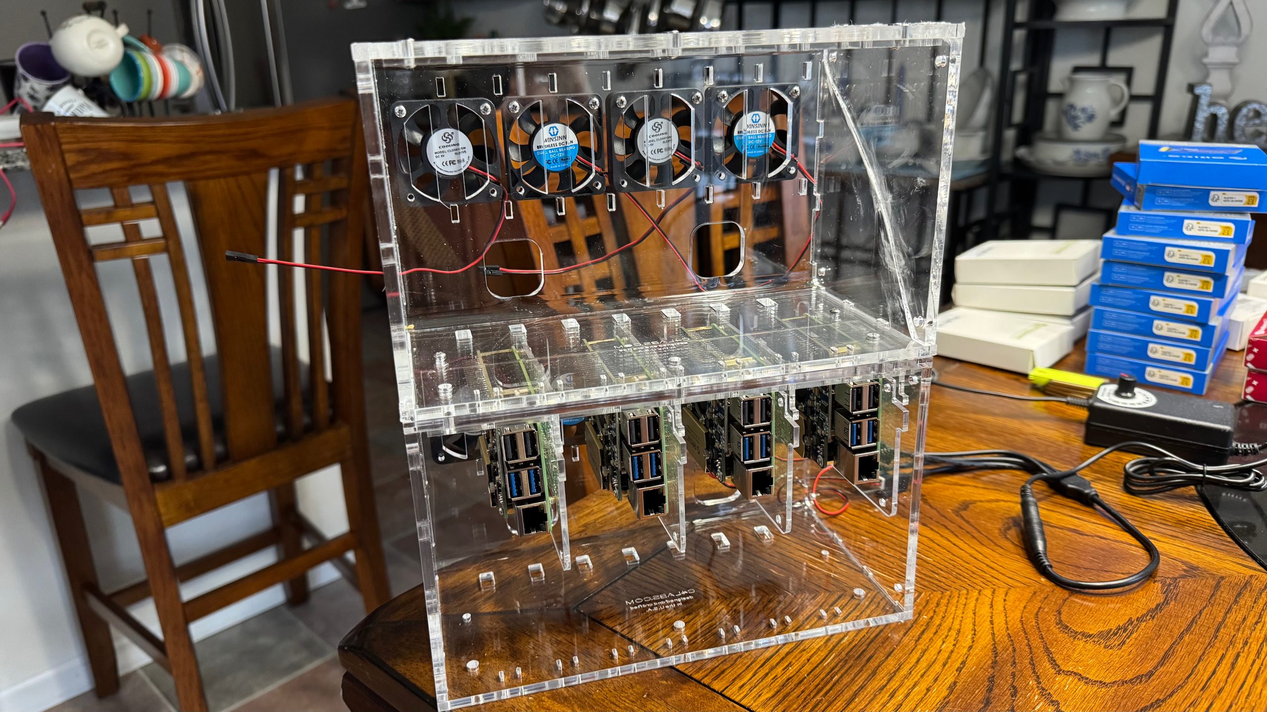

Insert the SPF+ to RJ45 module into one of the uplink SPF+ sockets of the switch. Put the switch in the bottom case. Then connect the Raspberry Pi 5s to the switch using the 1ft CAT6 cables. Connect the uplink port to your network. Finally power up the switch and all the Raspberry Pi 5s should boot up and the fans should start. Test all connections by using SSH and VNC to connect to all the nodes.


Software Setup
Before we can test the OpenMPI software that we installed, we must setup an ssh key so that the master node can log into all the clients without asking for username/password. We will first setup an ssh key on the master node, in my case it is balrog1.
First log into your master node using ssh. Then create an SSH public/private key pair in your home directory.
rich@balrog1:~ $ ssh-keygen -t rsa -b 4096
Press Enter to accept the default file location for storing the key (e.g., ~/.ssh/id_rsa). When asked for a passphrase leave blank for no passphrase.
Next copy the SSH public key to each of the other nodes in the cluster.
rich@balrog1:~ $ ssh-copy-id rich@balrog2.local
rich@balrog1:~ $ ssh-copy-id rich@balrog3.local
rich@balrog1:~ $ ssh-copy-id rich@balrog4.local
rich@balrog1:~ $ ssh-copy-id rich@balrog5.local
rich@balrog1:~ $ ssh-copy-id rich@balrog6.local
rich@balrog1:~ $ ssh-copy-id rich@balrog7.local
rich@balrog1:~ $ ssh-copy-id rich@balrog8.local
You'll be prompted for the password of the user on the destination server. Enter the password and the public key will be copied. Then use ssh to connect to the node. You should be let right in without being asked for a password.
It helps to distribute the software needed by the cluster if you have a file server that the nodes can access. You can connect to an NFS server, Apple server or any CIFS server. But a simpler approach is to use the SSH file system FUSE module to connect via SSH to your file server.
First you need to confirm your uid and gid that you want to use. Assuming your login, like mine “rich”, is the primary user of the node, the uid and gid should both be 1000. You can check with the “id” command to get the correct values.
rich@balrog1:~ $ id -u
1000
rich@balrog1:~ $ id -g
1000
You will need to install the SSHFS software on your nodes, create a directory to act as the mount point, then modify /etc/fstab so that the volume from your file share is mounted each time the node reboots.
rich@balrog1:~ $ sudo mkdir /mnt/OpenMPI
rich@balrog1:~ $ sudo chmod 777 /mnt/OpenMPI
rich@balrog1:~ $ sudo sshfs -o uid=1000,gid=1000.allow_other rich@10.0.1.201:/Volumes/OpenMPI /mnt/OpenMPI
rich@balrog1:~ $ ls /mnt/OpenMPI
rich@balrog1:~ $ sudo nano /etc/fstab
In the sshfs mounting command replace “10.0.1.201:/Volumes/OpenMPI” with the server name and path to the folder that you want to share on the server. The sshfs mounting command should ask for your server password. Then you can list the mount directory to confirm that it worked. Finally add the following entry to the end of your /etc/fstab file.
rich@10.0.1.201:/Volumes/OpenMPI /mnt/OpenMPI fuse.sshfs _netdev,uid=1000,gid=1000,allow_other,reconnect,defaults,IdentityFile=/home/rich/.ssh/id_rsa 0 0
It should all be on one line not on two lines as displayed.
Make sure that the IdentityFile argument points to the id_rsa file in your home directory that we created earlier. You will need to use ssh-copy-id to copy the public key to your server so that the auto mounter won’t need a password. In fact you will need to use ssh-keygen to create public/private keys on all the nodes and copy their public keys to the server with ssh-copy-id.
Unmount the server, reload the mount daemon, then mount all entries in the fstab file. You should then be able to list the mount point without having to enter a password.
rich@balrog1:~ $ sudo umount /mnt/OpenMPI
rich@balrog1:~ $ sudo systemctl daemon-reload
rich@balrog1:~ $ sudo mount -a
rich@balrog1:~ $ ls /mnt/OpenMPI
Again, you have to do this for all the nodes in the cluster so that they can all access the file server.
Testing the Cluster
To test the server and the MPI software we can follow the following steps:
Create an alias for your OpenMPI mount in your home directory on each node. This will make it a bit easier to run the software without having to enter the full mount point all the time. You can use the parallel ssh software to execute the same command on all the nodes. But first you will need to create a text file with all your nodes listed on your master node.
nodes.txt
balrog1.local
balrog2.local
balrog3.local
balrog4.local
balrog5.local
balrog6.local
balrog7.local
balrog8.local
Then from your master node you can run the parallel ssh command to create the OpenMPI alias.
rich@balrog0:~ $ parallel-ssh -h nodes.txt ln -s /mnt/RAID1/OpenMPI OpenMPI
[1] 21:03:53 [SUCCESS] balrog2.local
[2] 21:03:53 [SUCCESS] balrog1.local
[4] 21:03:53 [SUCCESS] balrog5.local
[5] 21:03:53 [SUCCESS] balrog4.local
[6] 21:03:53 [SUCCESS] balrog7.local
[7] 21:03:53 [SUCCESS] balrog8.local
[8] 21:03:53 [SUCCESS] balrog6.local
[10] 21:03:53 [SUCCESS] balrog3.local
The parallel-ssh command will be useful for installing software on all the nodes. For example we can update and upgrade the software on each node with:
rich@balrog1:~ $ parallel-ssh -h nodes.txt -l rich -A -i "sudo apt update && sudo apt upgrade -y"
Warning: do not enter your password if anyone else has superuser
privileges or access to your account.
Password:
Another example is to install software on all nodes. The parallel zip program can be installed with the following command:
rich@balrog1:~ $ parallel-ssh -h nodes.txt -l rich -A -i "sudo apt install -y pigz"
Warning: do not enter your password if anyone else has superuser
privileges or access to your account.
Password:
Now we can test that the OpenMPI software works to distribute work to all the nodes in the cluster. We will use the nodes.txt file with the mpirun command to execute a simple program like hostname on each node.
rich@balrog1:~ $ mpirun --hostfile nodes.txt hostname
balrog3
balrog8
balrog8
balrog4
balrog6
balrog3
balrog3
balrog4
balrog8
balrog4
balrog8
balrog3
balrog4
balrog5
balrog5
balrog5
balrog5
balrog1
balrog6
balrog1
balrog6
balrog6
balrog2
balrog7
balrog2
balrog7
balrog2
balrog1
balrog7
balrog7
balrog2
balrog1
The mpirun program will launch the program, hostname in this case, once for each CPU on each node in the nodes.txt file. We can create more specialized node files to control how many processes are created on each node. Copy the nodes.txt to the OpenMPI directory and change its name. Do this twice.
rich@balrog1:~ $ cp nodes.txt OpenMPI/nodes.txt
rich@balrog1:~ $ cp nodes.txt OpenMPI/nodes_1.txt
Modify nodes_1.txt to limit the OpenMPI software to one process per node.
nodes_1.txt
balrog1.local slots=1
balrog2.local slots=1
balrog3.local slots=1
balrog4.local slots=1
balrog5.local slots=1
balrog6.local slots=1
balrog7.local slots=1
balrog8.local slots=1
Running our test with this nodes file should only print the hostname once for each node.
rich@balrog1:~ $ mpirun --hostfile OpenMPI/nodes_1.txt hostname
balrog5
balrog1
balrog2
balrog6
balrog8
balrog3
balrog4
balrog7
Make a copy of nodes_1.txt that we can use for multi-threaded applications. In this use case, we want to run one master process on the master node and one multi-threaded client process on all the nodes including the master node. This new nodes_threaded.txt will be the same as nodes_1.txt but with the exception of a change to the first entry to slots=2 so that a master process and client process can run on the master node (first node).
Cluster Management
The most basic question we want to answer about our cluster is whether or not all nodes are responding on the network.
cluster_status.sh
#!/usr/bin/env bash
OpenMPI/cluster_status.pl OpenMPI/nodes_1.txt
OpenMPI/cluster_status.pl
#!/usr/bin/env perl
use strict;
use warnings;

# Ensure a filename is provided
if (@ARGV != 1) {
    die "Usage: $0 <filename>\n";
}

my $filename = $ARGV[0];

# Open the file for reading
open(my $fh, '<', $filename) or die "Cannot open file $filename: $!\n";

while (my $line = <$fh>) {
    chomp $line;

    # Extract system name (first word before a space)
    my ($system) = split(/\s+/, $line, 2);

    # Ignore empty lines and comment lines starting with #
    next if $line =~ /^\s*$/ || $line =~ /^\s*#/;

    my $status = "DOWN";

    # Ping the system (only 1 packet, wait 1 second)
    my $ping_result = `ping -c 1 -W 1 $system 2>/dev/null`;

    # Check if the ping was successful
    if ($? == 0) {
        $status = "UP";
    }
    printf("%-20s %s\n", $system, $status);
}

close($fh);
Now we can run the script cluster_status.sh from our home directory on the master node like this...
rich@balrog1:~ $ ./cluster_status.sh
balrog1.local        UP
balrog2.local        UP
balrog3.local        UP
balrog4.local        UP
balrog5.local        UP
balrog6.local        UP
balrog7.local        UP
balrog8.local        UP
Using the OpenMPI software it is easy to write some simple programs for cluster management. We can start with a program to check CPU load.
cluster_cpu.sh
#!/usr/bin/env bash
mpirun --hostfile ~/OpenMPI/nodes_1.txt ~/OpenMPI/cpu_load.pl | sort
OpenMPI/cpu_load.pl
#!/usr/bin/env perl
use strict;
use utf8;
binmode STDOUT, ':utf8';

use Sys::Hostname;
my $hostname = hostname();

my $mpstat = `mpstat 1 1`;

if ($mpstat =~ /all\s+.*?\s+([\d\.]+)$/m) {
	my $percent = 100 - $1;
	printf("%-31s %5.1f%% |%-40s|\n", $hostname, $percent, get_bar($percent, 100, 40));
}

sub get_bar() {
	my ($n, $max, $max_bar) = @_;
	my $blocks = int($n / $max * $max_bar);
	my $remainder = int(($n / $max * $max_bar - $blocks) * 8 + 0.5);
	my $bar = "\x{2588}" x $blocks;
	$bar .= chr(0x2588 + 8 - $remainder) if ($remainder != 0);
	return $bar;
}
The mpstat program used in the Perl script was installed when we installed the sysstat package. Now you can run cluster_cpu.sh from your master node and get a nice graph of the CPU load on all the cluster nodes.
rich@balrog1:~ $ ./cluster_cpu.sh
balrog1                           1.0% |█                                       |
balrog2                           0.8% |█                                       |
balrog3                           0.5% |                                        |
balrog4                           0.8% |█                                       |
balrog5                           0.8% |█                                       |
balrog6                           4.5% |███                                     |
balrog7                           0.5% |                                        |
balrog8                           1.0% |█                                       |
A similar graph of cpu frequency can be displayed with the following programs.
cluster_freq.sh
#!/usr/bin/env bash
mpirun --hostfile ~/OpenMPI/nodes_1.txt ~/OpenMPI/cpu_freq.pl | sort
OpenMPI/cpu_freq.pl
#!/usr/bin/env perl
use strict;
use utf8;
binmode STDOUT, ':utf8';

use Sys::Hostname;
my $hostname = hostname();

my $freq = `cat /sys/devices/system/cpu/cpu0/cpufreq/scaling_cur_freq`;

if ($freq =~ /^(\d+)$/m) {
	printf("%-31s %3.1fGHz |%-40s|\n", $hostname, int($1) / 1000000, get_bar($1, 2400000, 40));
}

sub get_bar() {
	my ($n, $max, $max_bar) = @_;
	my $blocks = int($n / $max * $max_bar);
	my $remainder = int(($n / $max * $max_bar - $blocks) * 8 + 0.5);
	my $bar = "\x{2588}" x $blocks;
	$bar .= chr(0x2588 + 8 - $remainder) if ($remainder != 0);
	return $bar;
}
Now you can run cluster_freq.sh from your master node and get a nice graph of the CPU frequency on all the cluster nodes.
rich@balrog1:~ $ ./cluster_freq.sh
balrog1                         1.6GHz |███████████████████████████             |
balrog2                         1.5GHz |██████████████████████████              |
balrog3                         1.5GHz |██████████████████████████              |
balrog4                         1.6GHz |███████████████████████████             |
balrog5                         1.5GHz |██████████████████████████              |
balrog6                         1.7GHz |████████████████████████████            |
balrog7                         1.5GHz |██████████████████████████              |
balrog8                         1.6GHz |███████████████████████████             |
Another graph of the memory used on each node can be displayed with the following programs.
cluster_mem.sh
#!/usr/bin/env bash
mpirun --hostfile ~/OpenMPI/nodes_1.txt ~/OpenMPI/mem_load.pl | sort
OpenMPI/mem_load.pl
#!/usr/bin/env perl
use strict;
use utf8;
binmode STDOUT, ':utf8';

use Sys::Hostname;
my $hostname = hostname();

my $vmstat = `free -b`;
my $used = 0;
my $total = 0;

if ($vmstat =~ /Mem:\s+(\d+)\s+(\d+)/) {
	my $percent = $2 / $1 * 100;
	printf("%-13s %8s/%-8s %5.1f%% |%-40s|\n", $hostname, siSuffix($2), siSuffix($1), $percent, get_bar($percent, 100, 40));
}

sub siSuffix() {
	my ($val) = @_;
	if ($val >= 1024 * 1024 * 1024 * 1024) {
		return sprintf("%.1fTi", $val / 1024 / 1024 / 1024 / 1024);
	} elsif ($val >= 1024 * 1024 * 1024) {
		return sprintf("%.1fGi", $val / 1024 / 1024 / 1024);
	} elsif ($val >= 1024 * 1024) {
		return sprintf("%.1fMi", $val / 1024 / 1024);
	} elsif ($val >= 1024) {
		return sprintf(".1fki", $val / 1024);
	} else {
		return sprintf("%d", $val);
	}
}

sub get_bar() {
	my ($n, $max, $max_bar) = @_;
	my $blocks = int($n / $max * $max_bar);
	my $remainder = int(($n / $max * $max_bar - $blocks) * 8 + 0.5);
	my $bar = "\x{2588}" x $blocks;
	$bar .= chr(0x2588 + 8 - $remainder) if ($remainder != 0);
	return $bar;
}
Now you can run cluster_freq.sh from your master node and get the memory used, maximum memory and a graph of the percent memory used on all the cluster nodes.
rich@balrog1:~ $ ./cluster_mem.sh
balrog1        914.6Mi/15.8Gi     5.6% |██                                     |
balrog2        918.9Mi/15.8Gi     5.7% |██                                     |
balrog3        902.0Mi/15.8Gi     5.6% |██                                     |
balrog4        920.0Mi/15.8Gi     5.7% |██                                     |
balrog5        921.1Mi/15.8Gi     5.7% |██                                     |
balrog6        918.6Mi/15.8Gi     5.7% |██                                     |
balrog7        920.4Mi/15.8Gi     5.7% |██                                     |
balrog8        919.6Mi/15.8Gi     5.7% |██                                     |
One final graph will be the temperature and fan speed using the following programs.
cluster_temp.sh
#!/usr/bin/env bash
mpirun --hostfile ~/OpenMPI/nodes_1.txt ~/OpenMPI/temp_load.pl | sort
OpenMPI/temp_load.pl
#!/usr/bin/env perl
use strict;
use utf8;
binmode STDOUT, ':utf8';

use Sys::Hostname;
my $hostname = hostname();

my $pwm = 0;
my $rpm = "---";
my $temp = "---";

$pwm = `cat /sys/class/hwmon/hwmon*/pwm1` if (glob("/sys/class/hwmon/hwmon*/pwm1"));
chomp $pwm;
$rpm = `cat /sys/class/hwmon/hwmon*/fan1_input` if (glob("/sys/class/hwmon/hwmon*/fan1_input"));
chomp $rpm;
$temp = `vcgencmd measure_temp`;
if ($temp =~ /temp=(.*)$/) {
	$temp = $1;
	$temp =~ s/'/\xB0/;
}

printf("%-21s %6s %5s RPM |%-40s|\n", $hostname, $temp, $rpm, get_bar($pwm, 255, 40));

sub get_bar() {
	my ($n, $max, $max_bar) = @_;
	my $blocks = int($n / $max * $max_bar);
	my $remainder = int(($n / $max * $max_bar - $blocks) * 8 + 0.5);
	my $bar = "\x{2588}" x $blocks;
	$bar .= chr(0x2588 + 8 - $remainder) if ($remainder != 0);
	return $bar;
}
Now you can run cluster_temp.sh from your master node and get the CPU temperature, fan speed and a graph that represents the PWM value being sent to the fan.
rich@balrog1:~ $ ./cluster_temp.sh
balrog1               63.1°C  4973 RPM |██████████████████████████              |
balrog2               43.9°C     0 RPM |                                        |
balrog3               45.0°C     0 RPM |                                        |
balrog4               42.2°C     0 RPM |                                        |
balrog5               48.3°C     0 RPM |                                        |
balrog6               44.4°C     0 RPM |                                        |
balrog7               46.6°C     0 RPM |                                        |
balrog8               41.7°C     0 RPM |                                        |
All these monitoring scripts can be run using the "watch" command to clear the screen and run the command every few seconds.
rich@balrog1:~ $ watch ./cluster_temp.sh

Projects
Here are links to some of the projects where I have used my Raspberry Pi 5 Cluster.
Resources
Raspberry Pi
How to build a Raspberry Pi cluster
Project MINI Rack
Open MPI Programming Basics